Introduction
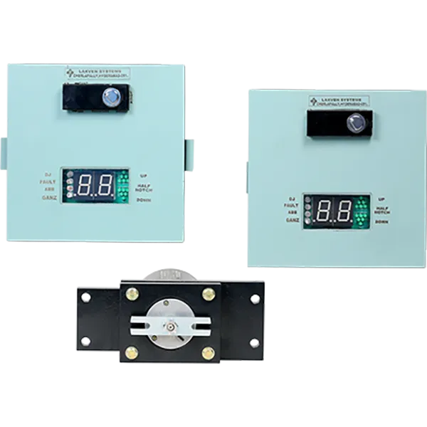
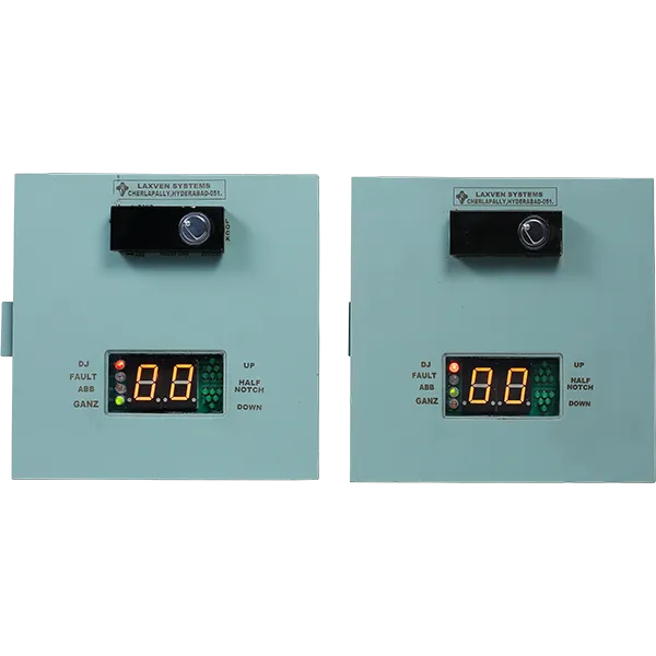
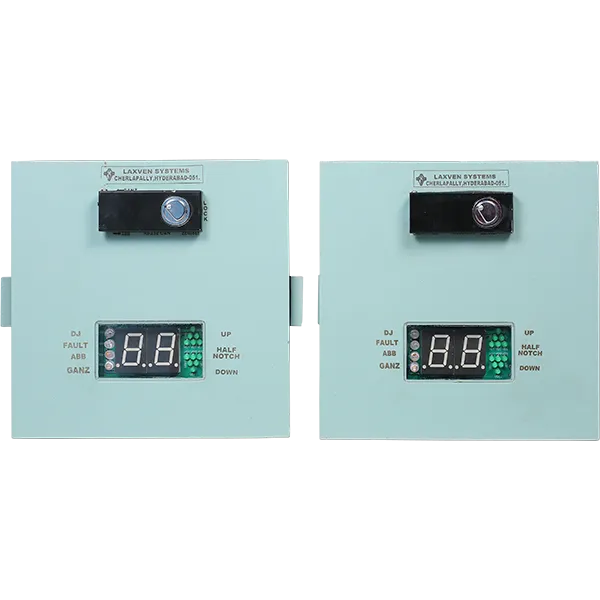
The Digital Notch Indicator is a microcontroller-based system designed for Electric Locomotives to monitor and record the position of the notch engaged, offering precise tracking and event recording. The system can record up to 10,000 events, aiding in post-incident analysis. The Seven-segment digital displays are placed in both cabs of the locomotive, offering clear visual indication of the notch position. Events like DJ trip, half-notch struck up, power on/off conditions, and more are stored with date and time stamps for later analysis. This system is compatible with both ABB and GANZ-type tap changers and can share data with other locomotive systems supporting CAN BUS communication.
System Overview
The Digital Notch Indicator ensures reliable and precise measurement of notch angles, with an accuracy of 0.01 degrees. The system stores and displays data for up to 10,000 events, offering FIFO (First in, First out) recording. It is designed for easy retrofitting, with mounting positions and wiring that match the existing system for compatibility. Data is downloadable via RS232, and the system supports communication with other systems via CAN BUS. The system is powered by the locomotive’s DC voltage range of 50V to 140V DC.
Salient Features
| Feature | Description |
| Microcontroller-based System | Highly accurate, stable, reliable, and low maintenance. |
| Self-Diagnostic & Fail-Safe | Ensures reliable operation with minimal maintenance. |
| Angle Accuracy | Measures the notch angle with an accuracy of 0.01 degrees. |
| Tap Changer Compatibility | Suitable for both ABB and GANZ type tap changers. |
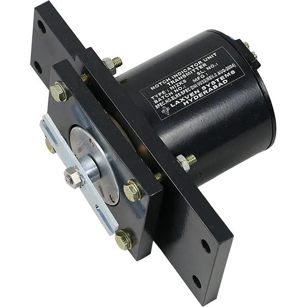
| Synchro Transmitter | Uses a highly reliable synchro transmitter for notch angle measurement. |
| Two-Digit LED Display | Displays the notch position clearly with a two-digit LED display. |
| Half Notch Indication | Allows locomotive crew to identify problems in the tap changer. |
| Null Point Alignment | Easy alignment of synchro transmitter’s electrical null point with tap changer’s null position. |
| Power Supply | Works with 50V to 140V DC power supply, suitable for all Indian railway locomotives. |
| Protection Features | Switch-mode power supply with reverse polarity, over-voltage, over-current, and short circuit protection. |
| Event Recording | Records up to 10,000 events (FIFO), with date and time stamps for post-analysis. |
| CAN BUS Communication | Shares data with other microprocessor-based systems via CAN 2.0 protocol. |
| RS232 Data Download | Allows downloading of recorded data to a PC using RS232 port. |
| User Configurable Parameters | Parameter entry can be configured via laptop. |
| Mounting & Retro Fitment | Mounting positions and wiring match existing systems for easy retrofitting. |
| Event Display & Indicators | Seven-segment LED displays for notch position and half-notch, with LEDs for events like DJ Trip. |
| Powerful Analysis Software | Windows-based software for user-friendly and efficient post-analysis of recorded data. |
Technical specification
| Parameter | Details |
| Power Supply Voltage | 50V to 140V DC from locomotive battery |
| Power Consumption | Less than 12 Watts |
| Angle Accuracy | 0.01 degree |
| Notch Measurement | Through synchro transmitter |
| Tap Changer Selection | Selector switch under lock |
| Null Alignment of Synchro | Push-to-ON switch under lock for alignment with tap changer null position |
| Event Recording Capacity | 10,000 events recorded with date & time stamp (FIFO) in non-volatile memory |
| Recorded Events | Power ON/OFF, DJ Trip, Half notch struck up, Zero setting of synchro, Internal faults |
| Display | 2 x 1-inch seven-segment LED display for notch, 1-inch UP & DOWN arrows for half-notch indication |
| LED Indicators | DJ Trip, ABB/GANZ selection, internal faults |
| Temperature Range | -5°C to +80°C |
| Data Entry | Through laptop |
| Downloading Recorded Data | Data can be downloaded to PC using RS232 |
| Communication Protocol | CAN 2.0 protocol |
| Analysis Software | Windows-based, powerful and user-friendly software for data analysis |


